
Common concept maps#
In this module we explore some common types of concept maps. In these maps you will often see similarities with the basic maps you saw in the first module. Each map has strengths and weaknesses for various types of information, and I discuss this in the descriptions. Like the last module, there are also some exercises at the end to test your knowledge.
Keep in mind you can also create your own style by combining elements of any maps. For example, Mind Maps use color extensively, so perhaps you could apply color to Flowcharts to identify differing types of steps.
One thing to hold onto before we start, because it changes how you should use every map below. A concept map is a layout — a way of organising and connecting ideas. The benefit of any of them comes from the active work of building the map (selecting what matters, organising it, and integrating it with what you know) and then redrawing it from memory to check — which is retrieval practice , the best-evidenced study method there is. The shape, the colour, the “look” of a map is not what makes it stick, and copying out a finished map does little. So as we go through each type, ask what it’s genuinely good for, and remember that a map you only admire is a map that mostly fooled you into feeling you’d learned.
The concept maps we examine in this module include:
-
Mind Maps. Created by Tony Buzan, these maps are probably the most well-known form of concept map.
-
IHMC concept maps. Created by educators, these maps are excellent for modeling knowledge.
-
Flowchart concept maps. These maps model the steps to follow to achieve some goal or decision.
-
Fishbone Diagrams. Also known as “cause and effect” or “Ishikawa” diagrams, these maps help you understand factors contributing to some problem or issue.
-
Pictorial concept maps. These maps use a pictorial or image form to help you understand the material.
-
Mandala concept maps. Mandala maps are usually circular and have centuries of tradition behind them. They’ve been adapted for modern use.
Mind Maps®#
Mind Maps® is a trademark of the Buzan Organization, Ltd. We have no affiliation with this organization. We reference “mind maps” as the output of the diagramming technique commonly known as “Mind Mapping”.
A mind map is a tree structure with one trunk and many branches. Mind maps expand on spider maps. A key difference between a spider concept map and a mind map is that a mind map doesn’t use labeled links — each branch combines the concept and the relationship. Here is an example of a mind map, and its topic is creating mind maps!
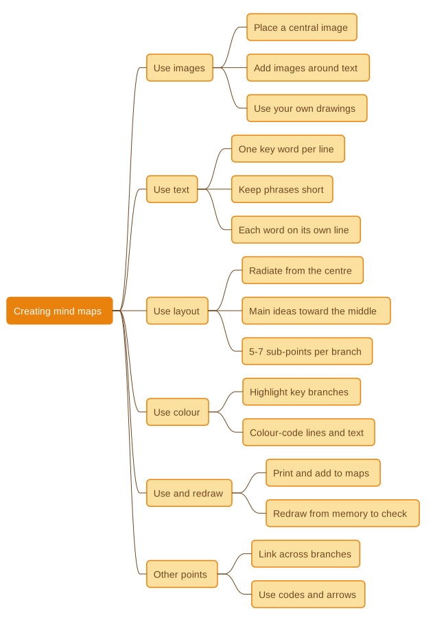
You may have heard mind maps sold with big claims — that they “engage the visual side of your brain,” tap “radiant thinking,” or let you remember far more just because they’re colourful and tree-shaped. Set those aside. The brain doesn’t split into a logical half and a creative half that a diagram unlocks (Nielsen and colleagues, 2013), and the shape of a map isn’t what makes it stick. So why include mind maps at all? Because the useful thing a mind map does is real, and worth being precise about:
-
They make you construct. To build a mind map you have to select what matters, organise it into branches, and integrate it with what you already know. That active processing — not the radial layout — is what builds understanding (Fiorella and Mayer, 2016). A map you copy off a slide does little; a map you build does the work.
-
They pair words with structure. When a short label and its position on the page reinforce the same idea, the two channels support each other rather than competing — the modest, genuine benefit behind “visual” learning. This only holds when the words and layout actually cohere; decoration for its own sake just adds clutter.
Be honest about the size of the effect. In one controlled study, students who mind-mapped a text recalled about 10% more than those who studied normally — a real gain, but a small one — and the mind-mappers reported lower motivation, because the technique took more effort than they felt it was worth (Farrand and colleagues, 2002). Mind mapping also costs time you could spend retrieving. So treat a mind map as one optional layout for organising and elaborating ideas, not as a memory engine. The benefits below are real, but they’re the benefits of organising and connecting material — which you could also get from a good outline or summary:
- A mind map shows at a glance how the sub-ideas hang off a main idea, which helps you see structure.
- It’s flexible — you can add a branch with little trouble.
- It holds a lot on one page, useful for an overview.
- The act of making one forces you to “cut to the chase” and pull out the essentials.
The strongest way to use any map: build it from memory. The single most useful thing you can do with a mind map — or any map in this module — is draw it from memory and only then check it against the source. That turns a passive diagram into retrieval practice , which is far and away the best-evidenced study method we have. Mapping that just copies the material feels productive but does little; mapping that makes you retrieve the material is where the learning happens. We call this retrieval mapping, and it’s the through-line for every map type here.
Creating mind maps#
Mind maps use color, layout, text and other elements to help distinguish concepts and relationships. The mind map example above has six main branches, all in different colors to make it easier for the viewer to distinguish among the main ideas. Each branch has a simple label (“Use images, Use color”, etc.) to make it easy to understand the actions to take. Then each main branch divides into sub-branches to further explain actions to take (“Use images throughout mind map”, etc.) Let’s explore each part of the mind mapping technique in more detail.
-
Use images. To start a mind map, represent the main topic with an image (square, rectangle or whatever works for you). Place the image in the center of the mind map. Use two or more colors in building the image. In our example, the main topic is “Creating Mind Maps.” The black text is on top of a gray rounded rectangular image. Use images in place of text where you have them or add them around the text to highlight. You might like to use your own drawings. Use them to highlight key points. Also, use clear and related images.
-
Use text. Be sure to use only one key word or idea per line. Also, keep your phrases short and break lists into separate points (Point 1, Point 2, etc.). Write or type the central topic in the image in the middle of your map. Use upper or lower case letters to make the topic stand out. Color the letters to make the words stand out; e.g., white on grey, etc. Make sure each word/image stands alone and is on its own line.
-
Use layout. All lines flow out from the central image. Beginning at the central image, the central lines radiate out like tree branches—they start out thick and become thinner as they spread outward. The lines should be the same length as the word and/or image. Use a hierarchy with main ideas towards the middle. Sub-points should branch from these main ideas (no more than 5-7 sub-points). Also, when needed use a numerical order (1, 2, 3) and work from the top down with a left to right order. Vary the size and color of the text, images, and branches to differentiate them and create visual interest. Don’t forget to use spacing in an organized and appropriate manner. If you have an auto-layout capability in your software, use that to create spacing.
-
Use color. Use color to highlight key branches and to group related ideas. Use colour to carry meaning — a consistent code for “definitions” or “examples,” say — rather than for decoration, so the colour is doing work and not just adding clutter.
-
Redraw it from memory. This is the step that matters most. Once you’ve made a map, put it away, then redraw it from memory and check what you missed. That’s retrieval practice , and it’s the difference between a map that merely looks finished and one that has actually moved the content into your head. Redraw it again after a gap of a day or two — spacing the redraws makes them stick harder still.
-
Other points. Connect ideas on different branches using lines and arrows to show relationships you’d otherwise miss. Use floating text (not connected to a branch) for ideas you can’t yet place — the act of deciding where they belong is part of the work.
Remember, a mind map is a draft, not a monument. Capture all the ideas you (or others) have, then edit and re-organise until the map captures exactly what you want to remember — and then test yourself on it rather than just admiring it.
Using mind maps#
Mind maps are useful for brainstorming. Brainstorming wants free association — lots of ideas, loosely connected, before you judge any of them — and a mind map’s open, branching format suits that: there’s always room to add another branch, and no obligation to commit to an order yet. That’s a genuine fit for the generating phase of thinking, distinct from the learning claims above.
You can also use a mind map for keeping notes, for developing a concept, or for getting an overview of an activity. Many activities can benefit from the mind mapping technique — just keep clear in your mind whether you’re using it to generate ideas, to organise them, or to learn them, because the third one only works if you go on to test yourself on what you’ve drawn.
To create a mind map, write down the central problem or idea you want to expand on. As you think of ideas, add branches to the central idea. Decide if these branches are major ideas and deserve their own branch or belong to an existing branch. At this point, don’t worry about format—just get your ideas down. It’s the creative phase, so scribble out ideas, move topics around, re-draw the map, and put links between ideas. In other words, do whatever gets your creative juices flowing to generate as many ideas as possible.
The very act of building a mind map helps you summarize any topic because it forces you to “cut to the chase”; i.e., focus on the essential elements of a subject. For example, while reading a book, highlight important points and ideas. Then, go back and create a mind map for each chapter. Pull out the main ideas and transfer them to your map. If you like, you can organize your map and ideas along the same lines as the chapter contents.
Mind maps are handy for organising any kind of information—books, letters, articles, meetings, and so on—because building one forces you to decide what relates to what. Use your summaries of content to create “master maps” that link to your references; e.g., more detailed mind maps, articles, books, files, websites. Remember the catch, though: organising material is only the first half of learning it. The map is the elaboration step; the retrieval step is closing it and recalling what was on it.
Example of a mind map#
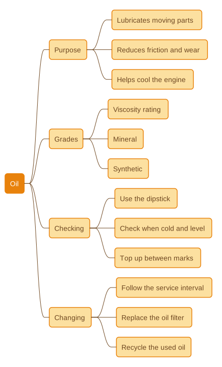
You can see another example of a mind map below. The mind map consists of a central word or concept. In this case, it’s about oil your car uses. Around the central word, there are several main ideas that relate to that word. Then each branch further divides into sub-branches. These branches list more information about oil. You can keep refining this map until it provides the information you need to remember about oil.
IHMC concept maps#
IHMC (Institute for Human and Machine Cognition) started in 1990 as an interdisciplinary research unit of the University of West Florida. Its research focuses on the broad concept of “human-centered” computing.
An IHMC concept map lays out how the parts of a topic relate, with every link named. That’s what it’s genuinely good for: making relationships explicit. Where a mind map leaves the connection between two branches implied, an IHMC map forces you to say what the connection is — “is composed of,” “is essential to,” “determines.” Naming the link is an act of elaboration : you can’t draw the line until you’ve worked out the relationship, and that working-out is most of the learning. The labelled structure also makes it easy to spot where your own understanding is vague — an unlabelled or hand-wavy link is usually a gap you haven’t filled.
The fundamental parts of an IHMC concept map are two or more concepts linked by relationships. We’ve seen this idea of labeled relationships in previous maps, however let’s cover them in more detail here. Here’s a simple example:
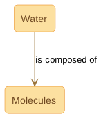
Concepts are usually events or objects. In our example, the key concept is water, and the immediate subordinate concept is molecules. The relationship between these two concepts is “is composed of.” IHMC calls the relationship a “proposition.”
Of course, water is a complex subject so additional subordinate concepts are required to explain the concept. These subordinate concepts are: 1) water’s importance to living things; 2) its composition; and 3) its various states and the examples of those states. Using this simple approach, you can build up a detailed concept map on water like the one below.
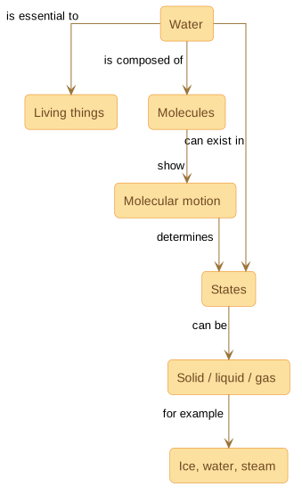
Laid out this way, the creator’s view of water and how its parts relate is quicker to take in than the same content buried in a paragraph — provided you read the labels, not just the boxes. The value isn’t that a picture is magically easier than words; it’s that the map has already done the work of separating the concepts and naming the relationships between them.
Some general guidelines for creating IHMC concept maps are:
-
Try to work from top to bottom. The main concepts should be at the top with subordinate concepts below them. It’s acceptable though to link across and up the map.
-
Keep your audience in mind. In our example above, some people might understand what a molecule is whereas others won’t. If your audience doesn’t understand what a molecule is, you might need to expand that concept as well.
-
You can link more than two concepts together. See the “can be” link under “states” in the example above.
-
You can use symbols instead of words. If a symbol better represents a concept, feel free to use it.
-
Use cross-linking. Feel free to link between parts of your map; for example, the “determines” link between “motion” and “states” above.
-
Try not to overlap links. If this occurs, you may need to re-arrange your diagram.
The “ozone” map below is another example. It lays out the relationships between ozone (a gas in the atmosphere), the earth, and human beings. Reading the labels, you can trace that “bad” ozone creates smog and may contribute to global warming, while “good” ozone is destroyed by CFCs and chlorine. A map like this is useful for untangling a topic where the same word (“ozone”) means two opposite things depending on where it sits.
While viewing the map below, did you notice that it’s not meeting an IHMC guideline? Which guideline is it not meeting?
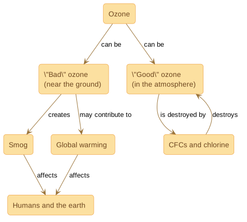
If you picked up the fact that it’s not working from the top to the bottom, you’re right!
Here’s another example of an IHMC map that models a business topic—managerial decision making. Read the following paragraph about this subject:
A systematic process helps to solve business and economic problems. Business and economic problems can be analyzed by use of a model. Variables and factors help to define that model. The model is quantitatively described using mathematical formulas, which, in turn, provide answers that lead to a course of action. Concurrently, a systematic process helps to solve business and economic problems, which are analyzed with mathematical representations. A systematic process also requires the definition of variables and factors, which are combined in the mathematical representations. As stated earlier, the mathematical representations provide answers. The answers lead to a course of action.
When you read that paragraph, you may have asked yourself, “What exactly did that mean?” In fact, you may have had to read it more than once to get an idea of its meaning. Well, look at the following concept map to see if it helps you understand the topic!
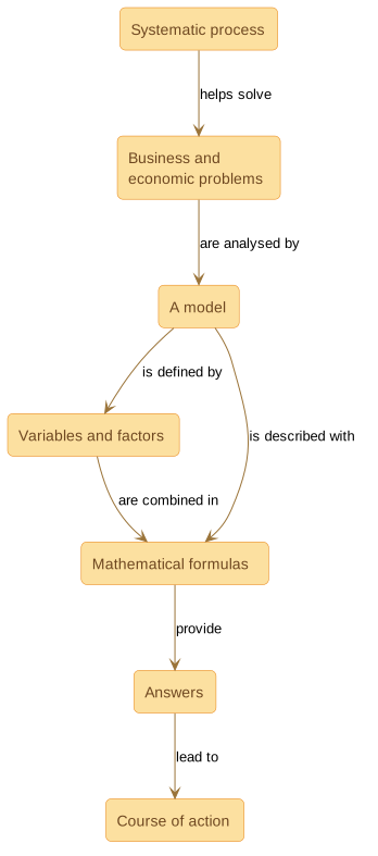
The map gives a clearer overall picture of the elements involved in managerial decision-making than the dense paragraph did. Notice why: the paragraph repeated itself and tangled the ideas together, while the map forced each concept into one box and each relationship onto one named link. That untangling is the benefit — and it’s a benefit you mostly bank while drawing the map, not while reading someone else’s.
For more examples of IHMC concept maps, visit http://cmap.ihmc.us/
Flowchart concept maps#
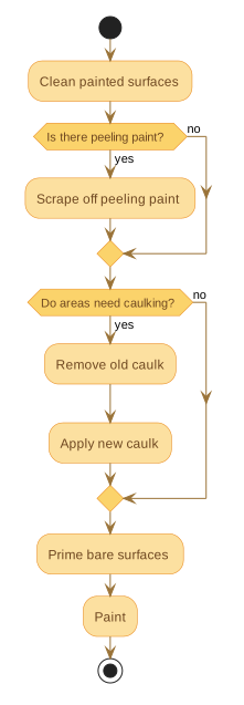 Flowcharts show how one concept or event leads to another. They’re genuinely good at one thing: making a procedure unambiguous — the exact order of steps, and what to do at each fork. If you can’t write the flowchart, you don’t yet understand the process, which is why drawing one is a useful test of your own grasp. Our example below shows a basic flowchart for painting a house. The flowchart explains a series of tasks that you have to perform and decisions that have to be made at certain points. For example, after cleaning all painted surfaces, the flowchart asks the question: Is there peeling paint? If the answer is Yes, then you need to scrape off the peeling/flaking paint before proceeding to the next decision point. If the answer is No, then you proceed directly to the next decision point: Do areas need caulking? Again, depending upon the answer you give, you will either remove old caulk and apply new caulk or you will proceed directly to the next decision point.
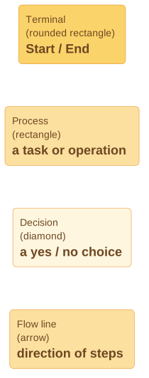
To make sure the flow of a concept is clear, flowcharts follow certain guidelines for the symbols to use. For example, the rounded rectangle or “Terminal” indicates the Start and End of a flowchart. A normal rectangle or square (“Processing”) shows data, information or arithmetic operations. “Clean painted surfaces” is an example of processing in the sample flowchart. The diamond shape is a “Decision point”. It represents an action or operation where there are two (or more) possible alternatives—Yes or No. The first decision point above involves peeling paint. If there is peeling paint, then “Yes”, you have to scrape it off before proceeding to the next decision point (Area need caulking?). If there is no peeling paint, then the alternative is “No, the paint does not need to be scraped”, and you can proceed directly to the next decision point. The lines and arrows indicate the flow and direction of the steps in a flowchart.
Below is a diagram that lists the symbols you can use when constructing a flowchart. I didn’t use all the symbols in the example, but you will find them in more complex concept maps of this type.
Here are guidelines for constructing a basic flowchart:
-
The flowchart should have a single main line of control, which connects START and END (or STOP).
-
It should have lines of control that enter symbols only from the top and leave symbols only from the bottom.
-
Avoid crossed or intersecting lines to maintain clarity in a flowchart. Usually, you can remove crossed lines by re-arranging the flowchart. However, if you can’t avoid crossing a line, use a “line hop.” A line hop is simply an arc in the line going over the crossed line.
-
Use an IF…THEN construct in your flowchart. For example, if the paint is peeling, then scrape the peeling paint. If the paint is not peeling, then proceed to caulking, etc. See the example on the previous page.
-
An IF…THEN diamond should have two, and only two, branches. The branch that goes to the right must eventually return (with an arrowhead) to the same line of control that its decision diamond lies on. All branches from a decision diamond should have a label indicating Yes/No (or True/False).
-
You can have more than two lines coming from a diamond, representing different options from the same decision. It’s often easier though if you keep the decisions to binary (yes/no or true/false) decisions.
-
A basic flowchart should have lines of control that proceed up a page only when in a loop. Usually all other lines go down or to the right.
Flowcharts for decision making#
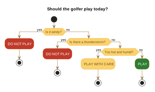 A decision flowchart is an arrangement of questions and answers that lead you to a decision based on certain inputs. These can be very simple or complex as the situation warrants.
The example shown gives you an idea of how a decision flowchart works. A golfer has to decide whether to play a round of golf according to the weather. The chart works through three yes/no questions and lands on an outcome: do not play, play with care, or play. Of course, if you’re a golfer or any other sportsperson you make these calls in your head all the time. For new or non-golfers, it might be interesting to learn that many golfers will play in the rain, but not in the wind — so wind sits at the top of this chart.
One key point for decision flowcharts is “efficiency”. Place decisions that have the greatest impact at the top of the flowchart. Taking the golf flowchart above, if most days are windy in your area, it makes sense to have the wind decision at the top. If, however, your local weather is mostly hot and humid, then it makes sense to have the “hot and humid” decision at the top.
Decision flowcharts are very similar to the standard flowcharts above. Use vertical lines of control. Use a horizontal line only as a right branch off a decision diamond. The chart proceeds down the page unless there is a right branch off a decision. Only a branch may go to the right, all lines of control should be vertical.
Fishbone concept maps#
Kaoru Ishikawa invented the “fishbone” concept map. Some people know these maps as “cause and effect” or “Ishikawa” diagrams. One of the fishbone map’s great uses is to help you search for the root causes of a problem and compare the relative importance of different causes of the problem. Ishikawa originally developed this type of diagram for use in the Kawasaki shipyards, but you can apply this format to a wide range of appropriate problems.
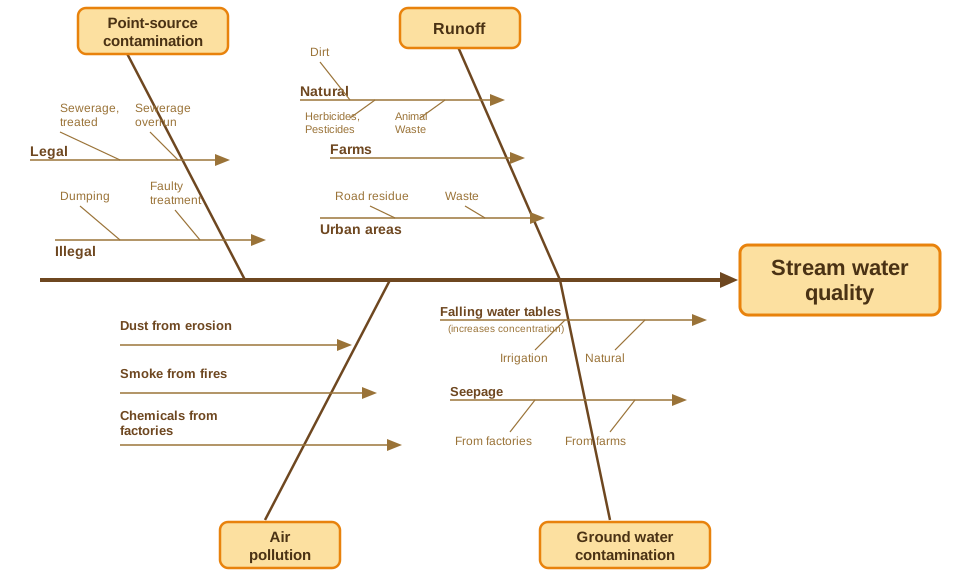
Essentially, fishbone maps help show the causes and effects present in various events and situations. Fishbone maps ask and try to answer key questions such as: What are the factors that cause X? How do they interrelate? Are the factors that cause X the same as those that cause X to persist?
In the example below, you can see that these questions are posed in terms of water quality. The map attempts to account for all the variables that influence stream water quality so that, eventually, solutions can be found to maintain high quality of water in that stream.
There are certain general steps you can follow to create an effective fishbone map:
-
Draw the central line and box and list the problem/issue you wish to study in the “head” of the fish (right). In our example, “Stream water quality” is the issue we’re analyzing.
-
Next, create and label each “bone” of the “fish”. In our example, the elements that affect water quality are listed in our diagram, but you can define any categories you like for a particular problem. Typical categories include:
-
The 4 M’s: Methods, Machines, Materials, Manpower
-
The 4 P’s: Place, Procedure, People, Policies
-
The 4 S’s: Surroundings, Suppliers, Systems, Skills
-
For each “node” (cause), think of what could be its effects and add them to the diagram. Use individual or group brainstorming to isolate the factors within each category that may be affecting the central issue.
-
Keep asking questions about each factor in a category to produce sub-factors. Ask the basic question, “Why is this happening?” Further facilitate the discussion by asking specific “who,” “what,” “when,” “where,” and “how” questions. Try to pursue each line of causality back to its root cause. Keep asking questions until you no longer get useful information.
-
Consider grafting relatively empty branches onto other branches. Also, if a branch is overcrowded, consider splitting it up into separate branches.
-
Once you have a sufficient amount of detail, analyze the results of your fishbone diagram. Look for items that appear in more than one category. These are your most likely causes of a problem.
If you are using fishbone maps for collaborating with others, here are some further tips:
-
First, make sure everyone agrees on the issue/problem before beginning the diagram.
-
If you’re holding a meeting, position the diagram so all group members can see it and contribute. A large piece of paper, flipchart or a whiteboard that can print copies for members is ideal.
-
Agree on the steps to take either to collect data verifying the causes or to eliminate causes through corrective action. Spend time between meetings gathering any additional information you need. Use forms such as checklists or surveys to collect information quickly.
Fishbone maps are very useful in many situations. You (or your group) can use them to identify possible root causes of a specific condition, effect or problem. You can also use them to sort out and relate interactions affecting a particular effect or process. Or you can analyze existing problems so corrective action can be taken.
Fishbone maps provide several benefits besides identifying the root causes of problems. First, they encourage group participation and make use of group knowledge to identify causes of problem. Second, they provide an orderly, easy-to-read format to diagram cause-and-effect relationships. Third, they indicate possible causes of variation in a process. Fourth, they increase knowledge of a process by helping you and team members to learn more about the factors at work and how they relate. Fifth, they identify areas where you should collect more information for further study.
Pictorial concept maps#
These maps present information in a landscape format as shown below. The picture landscape format works well for many subjects. My example shows the cycle of water in our climate.
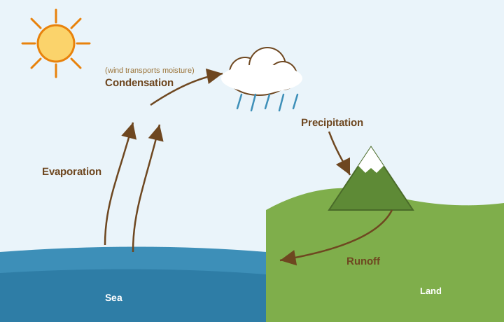
Wind transports moisture through the atmosphere. It condenses into clouds that then drop rain. The rain falls to the ground and runs off into a river, lake or ocean or in the form of ground water. Water then evaporates into the air, and the cycle continues.
A picture landscape format suits this kind of content well, because a cycle laid out in space lets you see the whole loop at once and grasp how the stages connect — easier than tracking the same sequence through a block of prose. It works best as a scaffold: take in the picture first, then read a fuller text explanation with the shape already in your head, and refer back to the picture if you lose the thread. The picture is doing dual-coding work here — image and words carrying the same structure — which only helps when the two genuinely match.
There is no right or wrong way to draw a pictorial concept map. The method is fluid and creative. There are general guidelines I can provide you, however. First, of course, you must have at least a basic knowledge of the subject. That means you have to collect concepts, ideas and any other information that’s helpful in organizing your thoughts about the subject. Once you have the basic information, rough out the relationships among ideas in an initial concept map. Play with this concept map by arranging and rearranging the ideas and the relationships until you have the map that you want. Then, add the pictorial representations of the concept map elements and play with those as well. When you’re satisfied with your creation, re-draw everything into a final map.
Mandala concept maps#
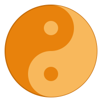 The word mandala means circle or wheel in Sanskrit. Various cultures have used mandalas for centuries as sacred and meditational art forms. For the purposes of concept mapping, a mandala map is a format of interlocking geometric shapes arranged around a centre. Perhaps the simplest and best-known mandala is the yin-yang symbol shown on the right.
In this case, one uncomplicated mandala stands for a great deal of thought and belief. It can represent light and dark, good and evil, order and chaos, and many other paired opposites according to the intentions of its creators. A mandala can also be a useful map when a topic has a natural centre with things arranged around it — a “what depends on what,” radiating from a core.
Let’s look at an example from the Memletics Accelerated Learning Manual: your learning state, the condition your body and mind are in when you try to learn. There’s a natural core (the things you can’t learn without at all) with further dimensions arranged outward toward the most mental, so it suits a circular layout. The manual organises your learning state into six dimensions, running from the most physical and foundational at the centre to the most mental at the rim:
- Cell — the fuel (innermost). Water, glucose, oxygen and basic nutrients. Nothing else works without it.
- Body — the machinery. General health, fitness, relaxation and your physical environment.
- Sleep — the consolidator. Where a lot of learning is actually filed, plus your daily and ~90-minute rhythms.
- Attention — the gate. You can’t learn what you never properly noticed; guard it from distraction.
- Emotion — the amplifier. Interest, curiosity, stress and mood steer what sticks.
- Mind — the operator (outermost). Mental health and fitness, relaxation, a positive attitude, and clear goals.
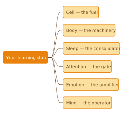
A note on this example. An earlier version of the manual drew the state as just three neat layers — cell, physical, and mental — wrapped in a mandala. The manual has since reworked it into the six dimensions above, because the old three-layer picture buried two of your biggest levers (attention and emotion) and treated sleep as a footnote (see Your learning state ). That rework also makes a fair point about a mandala’s limit: six dimensions don’t nest into clean concentric rings the way three do, so here we’ve shown the current model as a simple branching map instead. For a model this size, a plain list or an IHMC map often communicates better than forcing it into a circle — which is itself the lesson: match the map type to the material. The underlying message is the manual’s: your learning state is a set of dials, the foundational ones supporting the mental ones, and a problem low in the order ripples all the way up.
Mandalas can pack a fair amount of information into a single image organised around a centre, and they can serve as a “touchstone” when you read — if you lose the thread in the text, glance back at the picture to get your bearings. As with every map here, though, the lasting benefit comes from building one and then redrawing it from memory, not from looking at a finished one.
To create a mandala, start by placing the key concept in the center, then organise the rest in rings or segments around it. Look for relationships across the rings and reorganise, then relationships within a ring and reorganise again — for example, placing two things that naturally pair (water and oxygen as essential needs) opposite each other around the core. Those deliberate placements are themselves a form of elaboration: deciding where something belongs forces you to think about how it relates to everything else. Keep organising until every concept is positioned and labelled. Mandalas suit topics with a clear centre and a few rings; once you’re past three or four rings, reach for a different map.
Summary#
The concept maps in this module are variations on the basic maps. They give you flexibility in working out ideas and the relationships between them. Each is a layout — a delivery vehicle for organising and elaborating material. The learning still comes from the same place it always does: constructing the map yourself, and then redrawing it from memory to check. Mind maps expand on spider maps into a tree with one trunk and many branches; their benefit is the active selecting, organising and integrating you do to build one, not the radial shape. IHMC concept maps show two or more concepts linked by named relationships, typically with main concepts at the top and subordinate ones below; naming each link is where the thinking happens. Flowchart concept maps show how one step leads to the next, and are good for making a procedure unambiguous. Fishbone diagrams (also called “cause and effect” or “Ishikawa” diagrams) help a person or group search for the root causes of a problem and weigh their relative importance. Pictorial concept maps lay information out as a landscape, useful for seeing a whole cycle at once. Mandala concept maps arrange ideas in rings around a centre, suiting topics with a clear core and a few layers. Whichever you pick, the rule is the same: a map you build and test yourself on teaches you something; a map you only look at mostly just feels like it does.
Exercises#
The following exercises will give you the opportunity to practice making specialized concept maps. Each exercise will spell out the type of concept map, provide the necessary information, and ask you to construct a map for the specified situation. At the back of this manual, I’ve provided the concept maps that I drew up for each exercise. Remember that my concept maps are not only the “correct” solutions. As stated previously, such maps are flexible and can be highly individual. Simply use my solutions as guides.
Exercise 1—Mind Map#
Assume you’re a businessperson who needs to place an advertisement in a print magazine. Draw a mind map that shows the considerations involved in placing the ad (design, cost, copy, reach, location etc). Remember to color code the branches to help make the options stand out to your eye.
Exercise 2—IHMC concept map#
This exercise deals with a fountain pen. The objective is to construct an IHMC map that illustrates the structure of the pen and also shows the interaction of its parts (i.e., how the ink gets to the nib and tip). Below are the elements that need to be in the map.
-
A fountain pen is composed of a body, cap, reservoir, and nib
-
The nib has a slit. This helps ink to travel down to the tip.
-
The nib and reservoir interact with a feedbar.
-
Capillary action in causes ink to run from the reservoir, down the feedbar to the slit and then to the tip.
Exercise 3—Flowchart concept map#
Assume you’re driving down the road and see that your “low fuel” indicator light has illuminated. Construct a flowchart starting with the concept: “Low fuel light indicates need to fill tank.” From that concept, create a series of Yes/No decisions from the following points:
-
If the tank is low, you need to drive to a petrol/service station.
-
If you have a remote filler cap, you need to release it. If you don’t have one, then you proceed to the next step.
-
If you prefer a premium grade of gas/petrol, then you need to choose that grade. If not, choose regular.
-
Once grade is selected, insert nozzle and squeeze handle.
-
Fill until desired amount shows on pump display.
-
Replace the nozzle, fuel cap and pay.
-
Tank filled. You’re ready to drive on.
Exercise 4—Decision flowchart concept map#
Assume that you’re a loan officer at a bank. You have to decide whether or not to issue a loan to an applicant. Basically, the decision is Loan/No Loan. Here’s the information to include in the map:
-
No one who has been bankrupt can get a loan.
-
If income is less than $40K, applicant can’t get a loan.
-
If income is $40-$80K, check applicant’s present job tenure. Less than 1 year, no loan. If 3-5 years and didn’t pay credit cards on time, no loan. If cards paid on time, loan. More than 5 years, loan.
-
If income is greater than $80K, applicant can get a loan
Exercise 5—Pictorial landscape concept map#
This is a weather-related exercise that may call for some research on the Internet. Assume you want to show a simple cross section of a snow-producing cloud. Here’s a hint to get you started: snow forms at the top of the cloud. Color-code each cross-section of the cloud (e.g., the top snow-producing section of the cloud is gray, warm air is red, etc.). Remember that snow is produced by the collision of warm and cold air. Include the following information:
Here’s the information to work with:
-
Snow is produced by the collision of warm and cold air (a warm front colliding with a low-pressure center).
-
Draw a weather symbol for low-pressure system.
-
Draw a weather symbol for warm front.
-
Show the low-pressure system and warm front meeting.
-
Draw the cloud above the low pressure and warm front symbols.
-
Precipitation that begins as snow in the higher level of colder air melts into rain in the layer of air that’s above the melting point of ice— O degrees Celsius.
-
Rain hits another layer of cold air, re-freezes into snow, and falls to the ground.
-
Show snow falling from the cloud.